| 1) 3 BLADE ASSEMBLY: Make sure that if you
receive more than one propeller that you do not interchange
parts. Each propeller is individually balanced and if
interchanged it will be put out of balance. Please use figure
3 in the instruction book for part number references.
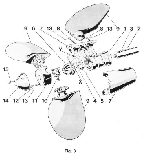
A) Fit the hub (1) to the propeller shaft (2). Be sure
that the key (3) is the proper dimension and that the hub
slides completely onto the shaft. If you are not sure,
remove the key and slide the hub onto the shaft making a
mark on the shaft where the hub stops on the shaft.
Re-insert the key and slide the hub on to the shaft, if it
slides up to your mark , it is fine. If not, you will need
to file down the sides or top of the key until the hub
slides completely onto the shaft.
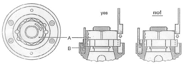
B) Tighten the nut (A) onto the shaft. Align the groves in
the base of the nut with the groves in the central hub, so
as to obtain two complete holes allowing insertion of the
pins (B). Insert the pins, then rotate the pins are as shown
in the drawing below, so as not to interfere with the
inserting of the central cone gear. One thread can be
exposed aft of the nut, if more than that is showing it will
be necessary to cut off the excess with a hack saw. If too
many threads are exposed it will raise the central cone gear
(6) and effect the performance of the propeller.
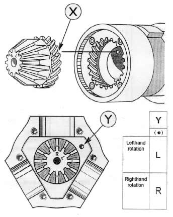
C) Insert the central cone gear (6) into the central hub
(1) as shown in figure 3VP. The cone gear has a block
between two teeth, this is the "X" mark. It will
fit into the central hub at only one place, where there is a
gap in the gear teeth.
D) Fill the two halves of the spinner (7) with grease. We
recommend Lubraplate model 130AA grease. Close the two
halves around the hub and tighten down the screws.
NOTE: DO NOT USE TEFLON GREASE it will
wash out very quickly.
E) Locate the mark on the top inside of the spinner (a
small drill hole). This is the "Y" mark in the
drawing below. Rotate the spinner until the "Y"
mark on the spinner coincides with the correct letter on the
top of the cone gear. "R" is for a right hand
rotation shaft and "L" is for a left hand rotation
shaft. (Shaft rotation is determined from the stern of the
boat looking forward).
NOTE: It is helpful to make a
mark between the spinner and the exposed part of the central
hub, or tape them so that any rotation can be noted and
corrected. If the spinner is rotated before the blades are
attached it will alter the blade angle.
F) Insert the three blades onto the three pins of the
spacer (10). Fill the end cap (11) with grease and put the
blades into the three seats of the end cap.
NOTE: Make sure that the numbers
on the blades correspond to the numbers on the spacer and
the numbers on the end cap 1 to 1, 2 to 2, and 3 to 3.
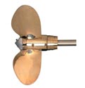
G) Move the blades to the feathered position, making sure
that the rounded trailing edges of the blades are aft as
shown in figure 3 of the instruction manual. Slide the end
cap and feathered blades onto the spinner, make sure that
the numbers on the blades and spinners match. Next tighten
down the end cap with the screws.
NOTE: Check to see that the
spinner did not rotate. If it did pull the blades back
1/4" and then realign the mark between the spinner and
hub. Make sure that when the blades go on to the spinner
that they are fully feathered.
H) To make the blades rotate more freely it is advisable,
after tightening all the screws, to give some bedding blows
on the spinner and blades with a plastic or wooden mallet.
I) To make sure that the screws will not loosen insert a
cotter pin into the head of each screw. Put them in so that
if the screw were to loosen it would hit the cotter pin as
shown in figure 5 of the instruction manual. Cut the cotter
pins to a length of 1/4" and put them in. A light tap
with a hammer on the head of the pin will spread the ends
open, it not use a screw driver to spread them apart.
J) Make sure that the propeller is protected from
electrolytic corrosion by using "mil spec" zinc
anodes on the propeller shaft. If the propeller has been
assembled properly:
- The blades must rotate freely and stop at the blade
angle you selected.
- In the feathered position the blades must line up
perfectly as in figure 6.
- The propeller must never rotate as shown in figure 7.
2) PITCH ADJUSTMENT This is a critical step, make
sure that you know what pitch to set the propeller at, either
by your old propeller or by your engine and reduction ratio.
- The pitch is adjustable from 10 to 30 degrees of blade
angle.
- Figure 1 shows the conversion from inches of pitch to
degrees of blade angle.
- To properly convert from inches to degrees follow steps
A thru C.
A) Determine the diameter of your propeller
B) Go down the column that corresponds to your propeller
diameter until you find the desired amount of pitch.
C) Cross reference this pitch in inches to the blade setting
angle directly across the chart and you will have the desired
blade angle.
| Propeller
Diameter |
|
|
15" |
16" |
17" |
18" |
19" |
20" |
21" |
22" |
23" |
24" |
25" |
26" |
| B |
10o |
4.9 |
5.2 |
5.5 |
6.0 |
6.3 |
6.7 |
7.1 |
7.4 |
7.7 |
8.0 |
8.3 |
8.6 |
| L |
11o |
5.5 |
5.8 |
6.2 |
6.6 |
7.0 |
7.4 |
7.8 |
8.1 |
8.5 |
8.8 |
9.2 |
9.5 |
| A |
12o |
6.0 |
6.4 |
6.8 |
7.2 |
7.6 |
8.0 |
8.4 |
8.8 |
9.2 |
9.6 |
10.0 |
10.4 |
| D |
13o |
6.6 |
7.0 |
7.4 |
7.8 |
8.2 |
8.7 |
9.1 |
9.6 |
10.0 |
10.4 |
10.8 |
11.3 |
| E |
14o |
7.1 |
7.6 |
8.0 |
8.4 |
8.8 |
9.4 |
9.8 |
10.4 |
10.8 |
11.2 |
11.6 |
12.2 |
|
15o |
7.6 |
8.1 |
8.6 |
9.1 |
9.6 |
10.1 |
10.6 |
11.2 |
11.7 |
12.1 |
12.6 |
13.1 |
| S |
16o |
8.1 |
8.6 |
9.1 |
9.8 |
10.3 |
10.8 |
11.3 |
12.0 |
12.5 |
13.0 |
13.5 |
14.0 |
| E |
17o |
8.7 |
9.2 |
9.8 |
10.4 |
10.9 |
11.5 |
12.1 |
12.7 |
13.3 |
13.8 |
14.4 |
15.0 |
| T |
18o |
9.2 |
9.8 |
10.4 |
11.0 |
11.5 |
12.1 |
12.8 |
13.4 |
14.0 |
14.6 |
15.2 |
16.0 |
| T |
19o |
9.8 |
10.4 |
11.0 |
11.7 |
12.3 |
12.9 |
13.7 |
14.2 |
14.8 |
15.5 |
16.1 |
16.9 |
| I |
20o |
10.3 |
11.0 |
11.6 |
12.4 |
13.0 |
13.7 |
14.5 |
15.0 |
15.6 |
16.4 |
17.0 |
17.8 |
| N |
21o |
10.9 |
11.6 |
12.3 |
13.0 |
13.7 |
14.4 |
15.3 |
15.9 |
16.6 |
17.3 |
18.0 |
18.8 |
| G |
22o |
11.4 |
12.2 |
12.9 |
13.6 |
14.3 |
15.1 |
16.0 |
16.8 |
17.5 |
18.2 |
18.9 |
19.8 |
|
23o |
12.0 |
12.8 |
13.6 |
14.3 |
15.1 |
16.0 |
16.8 |
17.6 |
18.4 |
19.2 |
20.0 |
20.8 |
| A |
24o |
12.5 |
13.4 |
14.2 |
15.0 |
15.8 |
16.8 |
17.6 |
18.4 |
19.2 |
20.2 |
21.0 |
21.8 |
| N |
25o |
13.2 |
14.1 |
15.0 |
15.8 |
16.6 |
17.6 |
18.5 |
19.3 |
20.1 |
21.1 |
22.0 |
22.8 |
| G |
26o |
13.8 |
14.7 |
15.7 |
16.6 |
17.4 |
18.4 |
19.3 |
20.2 |
21.0 |
22.0 |
22.9 |
23.8 |
| L |
27o |
14.4 |
15.4 |
16.4 |
17.3 |
18.2 |
19.2 |
20.2 |
21.1 |
22.0 |
23.0 |
24.0 |
24.9 |
| E |
28o |
15.0 |
16.0 |
17.0 |
18.0 |
18.9 |
20.0 |
21.0 |
22.0 |
23.0 |
24.0 |
25.0 |
26.0 |
|
29o |
15.6 |
16.7 |
17.8 |
18.8 |
19.8 |
20.9 |
21.9 |
23.0 |
24.0 |
25.1 |
26.2 |
27.1 |
|
30o |
16.2 |
17.3 |
18.5 |
19.6 |
20.6 |
21.7 |
22.8 |
24.0 |
25.0 |
26.1 |
27.3 |
28.2 |
| Inches
of pitch |
Pitch adjustment is very simple on the V.P. model, and
can be done with the boat in or out of the water in a matter
of seconds. Refer to the figure below.
Once you have determined the pitch and rotation to set
the propeller at, pull back on the adjustment ring and
rotate it to the correct degree of blade angle for that
rotation. Once the correct setting aligns with the degree
reference mark push it back into place. The pitch is now
set. As an example the setting for the propeller in the
drawing below is 22o for a right hand rotation propeller or
18o for a left hand rotation propeller.
Figure 2 below shows degrees of blade angle not inches
of pitch.
To convert from inches of pitch to blade angle use figure 1.
3) TROUBLE SHOOTING If the propeller feels stiff
or has a hard spot in the rotation systematically go through
the points below.
A) If the propeller does not rotate freely, remove some
of the grease from the spinner and reassemble.
B) Sometimes it can happen that a small piece of metal
or a burr enters the gears, or a piece of the propeller
has been dinged; in this case the blade movement can
become hard. It is necessary then to do as follows,
referring to figure 8.
1) Open the propeller and assemble it again after
having taken the central cone gear (6) out, so that the
blade and the hub rotation are independent. If the hub
rotation is hard, remove 0.01 mm from surfaces
"A" with an emery cloth. On the contrary if
the blades rotation is hard, remove 0.01 mm from
surfaces "B" of the spacer using emery cloth
wrapped around a flat file. Try until both hub and
blades rotate freely.
4) PROPELLER USE The Max Prop works automatically.
By putting the engine in gear the blades will engage in
either forward or reverse. The best way to feather the
propeller is;
- Power at 2 to 3 knots in forward.
- Kill the engine while still engaged in forward.
- When the engine has stopped, if the shaft is still
spinning engage the transmission in reverse to stop the
freewheeling.
You can check to see if the propeller is feathered or not
by taking the engine out of gear. If the propeller is not
feathered the shaft will freewheel like with a fixed blade
propeller.
In that case start the engine again and repeat the three
steps. If your propeller has been greased properly it will
feather in a fraction of a second as soon as you stop the
shaft from freewheeling. Once the prop is feathered, you can
either leave the transmission in gear or out of gear, it
does not matter. DO NOT kill
the engine while in reverse. In this case the blades will be
in the reverse position and will not feather. You can
actually use this feature to drive a shaft alternator.
5) PROPELLER MAINTENANCE The Max Prop needs to be
regreased a minimum of once every two years. We recommend
Lubraplate "130 AA" Grease, it is inexpensive and
performs better than many other greases.
There are two holes in the spinner of the propeller to
grease. Remove the set screw from the forward hole with a #3
metric Allen wrench and screw in the zerc tower, attach your
grease gun and fill the propeller with grease until the
grease starts to come out between the hub (#1) and the
spinners. Replace the set screw and remove the set screw
from the more aft hole. Reinstall the zerc tower and attach
your grease gun and fill the propeller with grease until the
grease starts to come out between the blades and the
spinners. Remove the zerc tower and reinsert the set screw
into the propeller. Do not leave the zerc tower in the
propeller.
- With each pump of the grease gun rotate the propeller
from forward to reverse to allow the grease to work
through the propeller.
- The numbers above are from Figure 3 at the beginning
of this Max-Prop Manual.
- Make sure that you always keep the zinc anodes in good
condition. They must be replaced at least once a year or
as needed. The propeller must be protected by a lot of
zinc. When replacing it make sure that you clean the
contact point between the zinc and propeller shaft. Use
a wire brush or fine sandpaper to clean the shaft and
the inside diameter of the zinc to give the zinc good
contact with the propeller.
6) PROPELLER REMOVAL In order to remove the
propeller you must first remove the spinner and nut. Be sure
only to pull from outside the hub (figure 9). If the
surfaces on the hub are hit or dinged it can effect the
performance of the propeller.
7) WARNING It is important to follow the
instruction below carefully so as to avoid a shock to the
gears on the blades and cone gear, that could be damaging to
the teeth.
1) When going from forward to reverse and the opposite,
it is necessary to idle down and shift at low RPM's
between gears.
2) The propeller body must always be completely filled
with a very fluid grease. This is so when you reverse
direction the rotation will be smooth with no binding.
Binding points will produce a shock and could damage the
gears.
|