Existing Trace 1500DR Inverter Testing
As purchased the only 110V power aboard came from a Trace 1500DR
Inverter with a build code of 1997. Most likely this was installed
prior to the boat heading from the Med to the Carrabiean by her 2nd
owner. The overall system has a single circuit throughout the boat
which was run through a small panel under the nav station seat. The
wiring uses what looks to be stranded three conductor #12 wire which is
yellow (looks much like drop lamp wire). The 110V AC system could be
provided power either from a step down transformer from the 230V shore
power or via the inverter directly. While the inverter was capable of
being used as a battery charger for 24V it was never wired up to shore
power in any way. Probably the goal was to almost always run the
inverter to make sure that the 110V circuit was only getting clean 60Hz
power.
The inverter was found to not be able to handle loads of more than
about 50 watts without shutting down shortly after I purchased the
boat. It appeared to work correctly with small loads. Sometimes by
resetting the inverter completely (removing power and allowing to
discharge for several hours) it would work with larger loads (up to
perhaps 300 watts) for a time and then would start having trouble
again.
During one of these cycles it ate a Nook which is surprising as the
Nook power supply has a very wide range of power inputs for it's power
supply and it is only using a USB type power plug. At this point I
realized that even if I could get the unit working correctly (they are
no longer manufactured) I would most likely not trust it.
After realizing that the waveform was this "simple" I decided that I
need to migrate to the newer "True Sine Wave" inverters to ensure that
modern electronics will not be damaged by the onboard power system.
The inverter has been removed and I am actively trying to decide
between a Victron Energy based system or a Mastervolt based system.
Most likely I will end up with a mastervolt based system and have
recently purchased a 350 watt inverter to power the navigation system
independently from the rest of the boat.
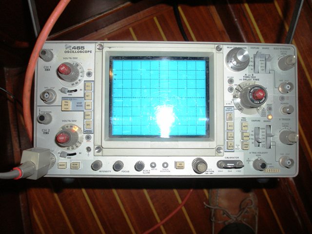
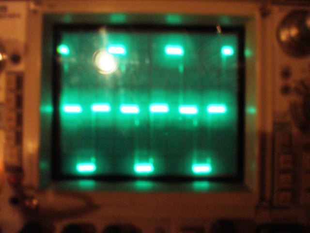
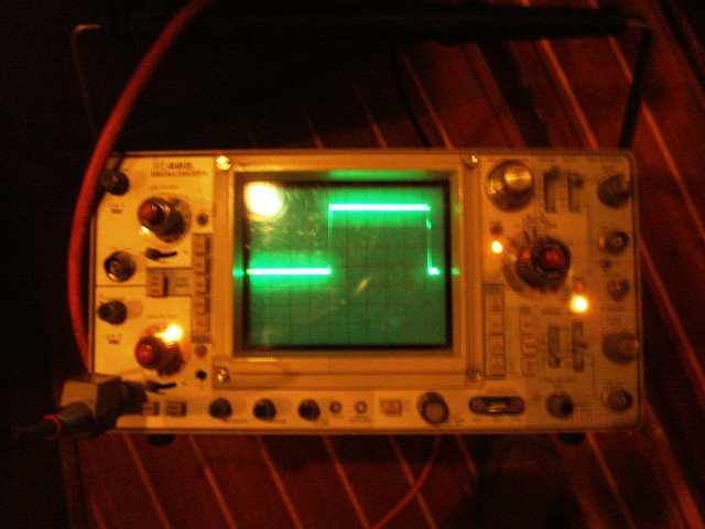
However, as a point of interest I did document the following
oscilloscope traces while while trying to debug the unit.
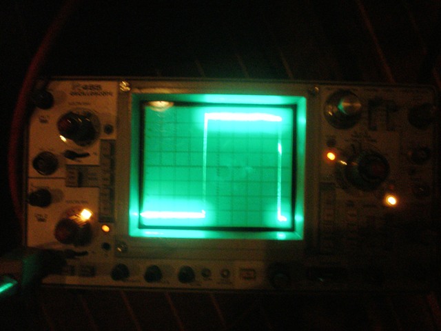
This is what a "modified sine wave" inverter can look like. Basically
it is square pulses with the width of the pulse adjusted to make the
RMS voltage approximately correct.
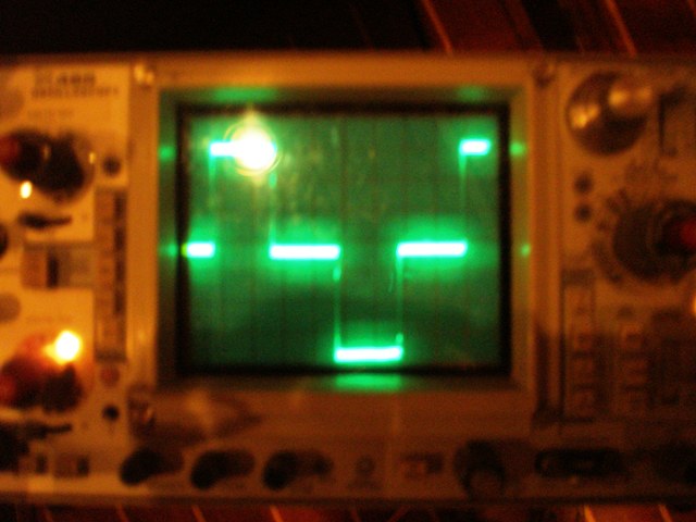
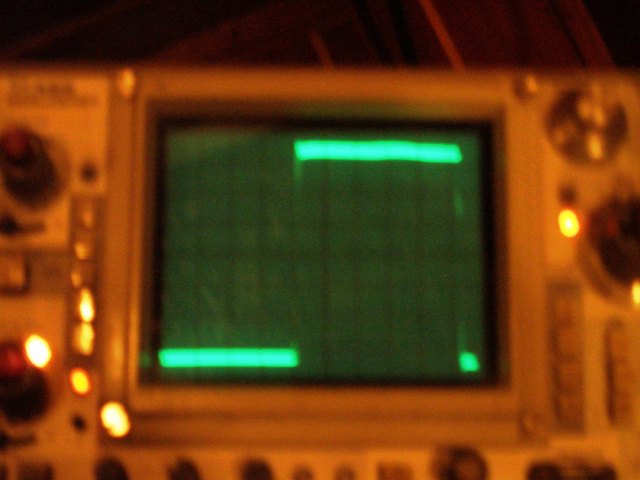
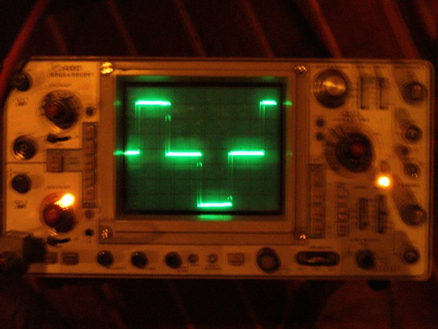
This is a close up of the "Modified Sine Wave" note that waveform
spends a significant time at 0V
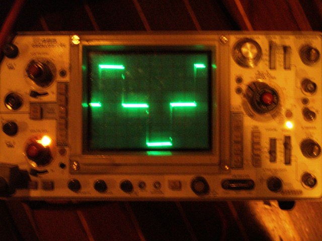
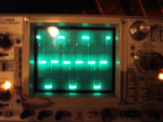
This is a close up of a single positive pulse in the waveform.