At any rate, the original stuffing box was very difficult to get to just the right combination of grease and pressure and not have the stuffing box leak or overheat. I had one case where after rebuilding the stuffing box everything seemed very good, a very slight drip while underway and nothing when the shaft was not turning and had several trips that way. Then it became hot enough to feel it walking over the floorboards right above it (just a bit of random warmth) and a wet rag would sizzle when in contact. I was able to loosen it up and cool it down with no harm done. Somehow the combination of modern packing and the old grease caused significant intermittent issues with cooling. If I had taken it all apart out of the water, removed all of the grease and gone to a modern packing / lubricant it probably would have been fine.
However, I have had great success previously with the PSS dripless packing system from PYI. While the unit for the CAL 35 was the smaller size the concept and installation are very similar. In the case of the Oyster 55, the shaft size is 1.5" and the stern tube outside diameter is 2.5". The larger bellows assembly does result in the clearance between the bellows and the bilge area directly below the stuffing box being tight but with some minor sanding and painting I was able to get sufficient clearance to avoid abrasion issues in this area.
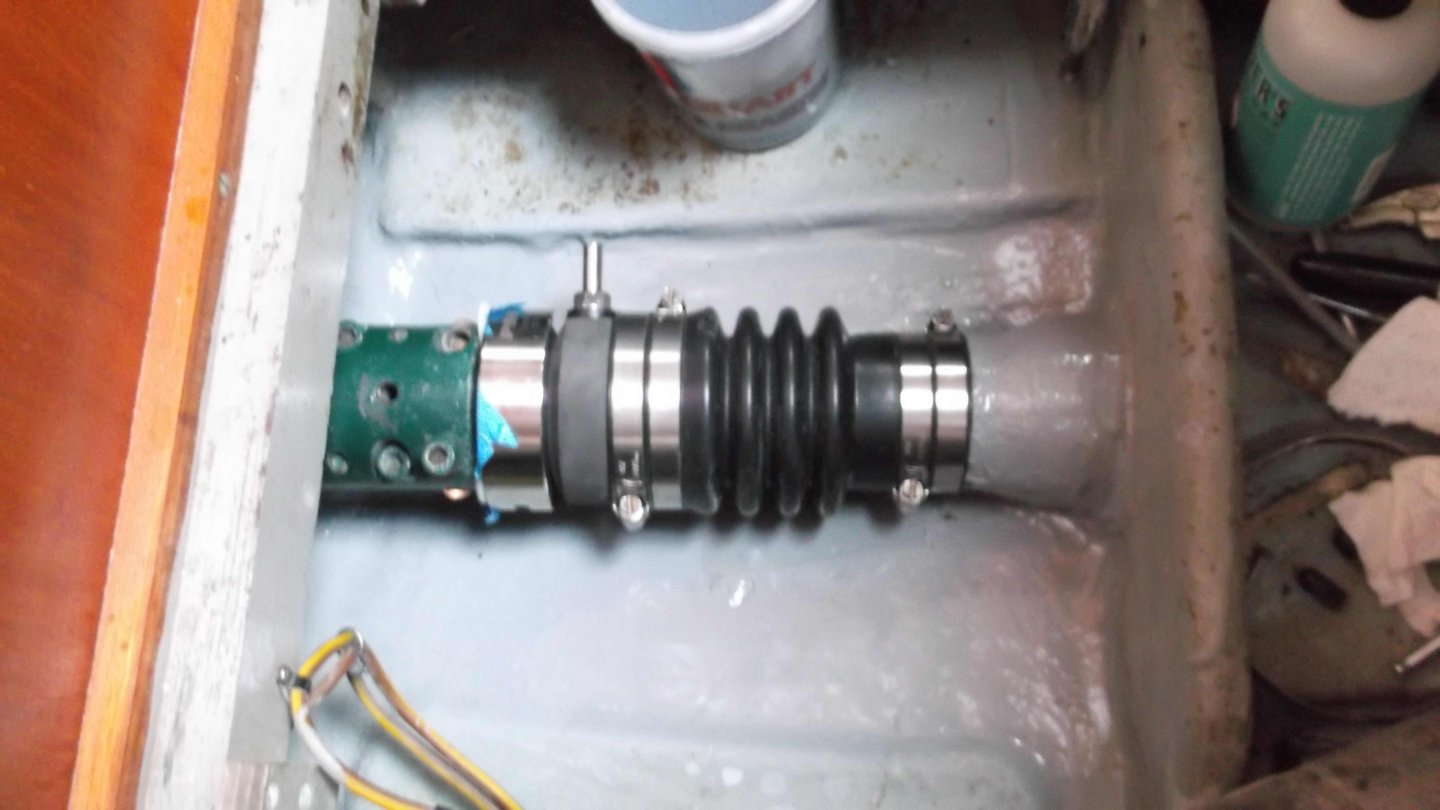
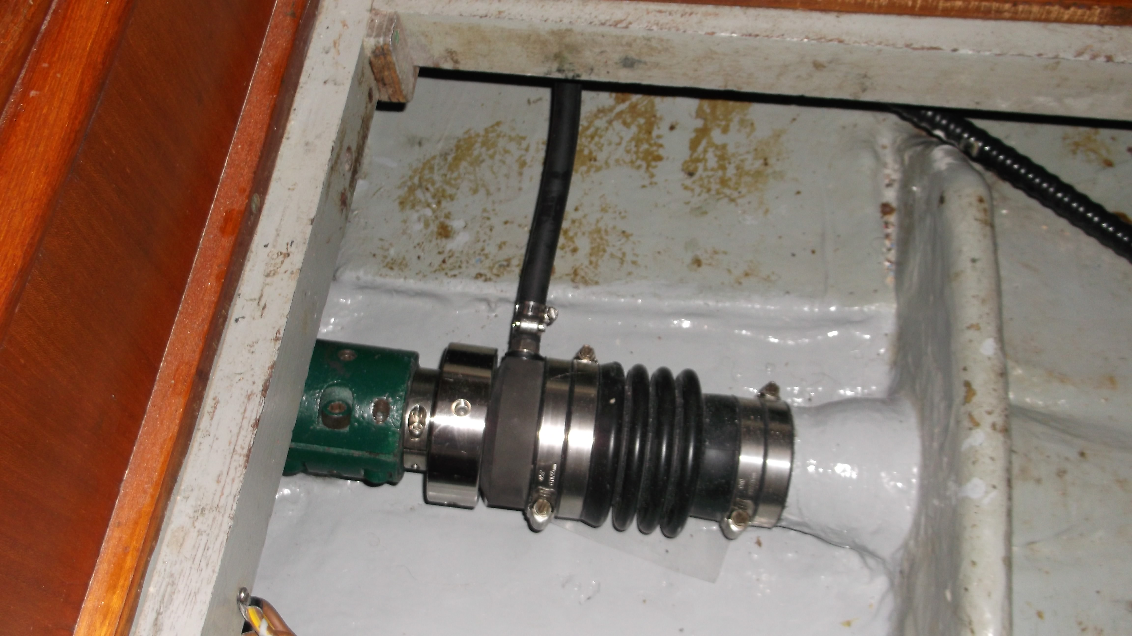
This image is the first mockup to determine if the new stuffing box will in fact fit in the location of the previous stuffing box. Note that the forward end of the stainless steel rotor has been covered in blue painting tape to keep it from being scratched up by the aft end of the Aquadrive thrust bearing assembly. The shaft has not been re-installed into the boat at this point.
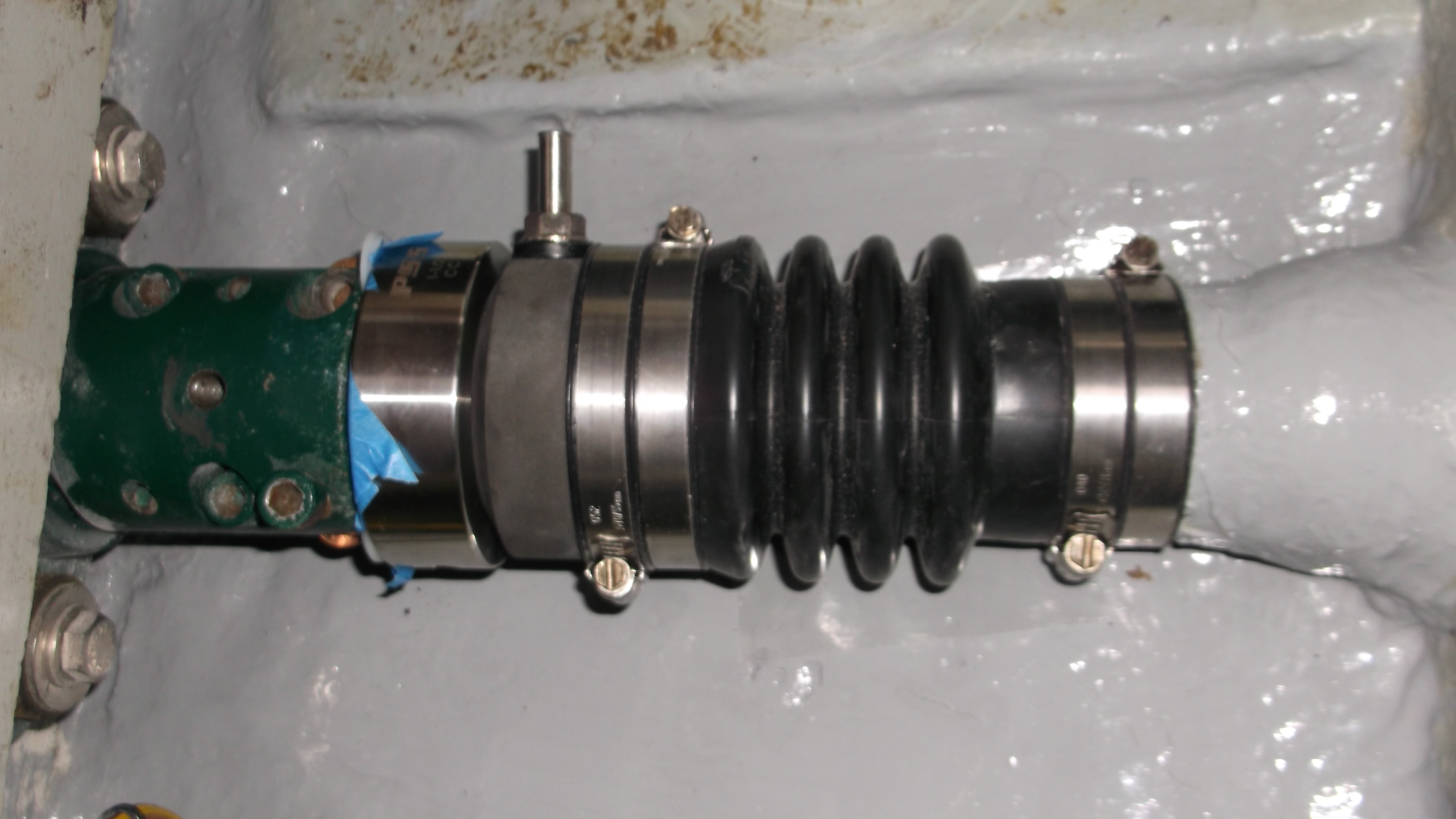
A closeup of the mockup installation. Note that I had to change the orientation of all of the hose clamps to ensure access for adjustment. The bellows is compressed 0.325 inches at this point. The correct total bellows compression is 1.0 inch minimum and thus I need at least 0.675 inches of distance between the stainless steel rotor and the aft end of the Aquadrive thrust bearing assembly.
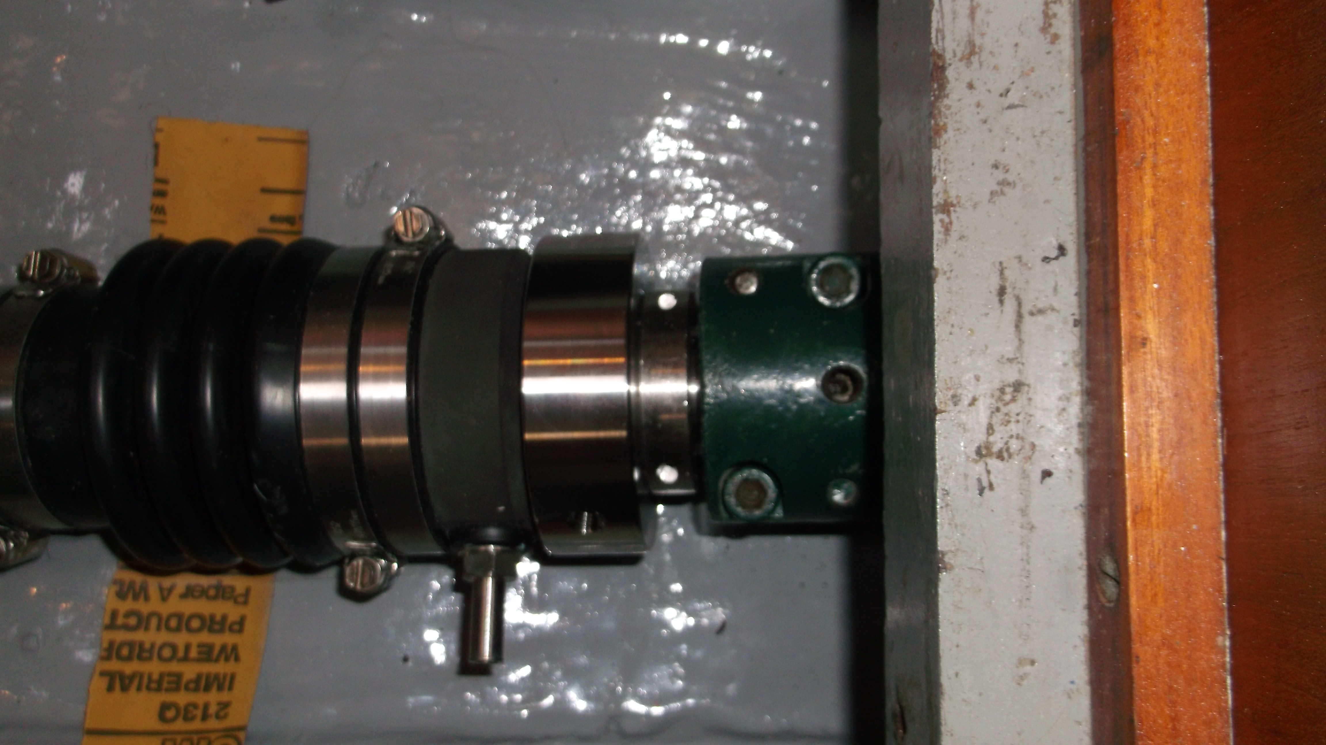
Here the shaft has been installed and the shaft clamp installed. The clamp is 9/16 inch thick or 0.5625 inches leaving 0.1125 inches of exposed shaft at the minimum 1" of bellows compression. Thus a bit over a tenth of an inch of exposed shaft is about right. Note that when working with these types of rotating seals it is essential to secure the shaft if the thrust bearing is removed from the boat. On many boats removal of the transmission could allow the shaft to move forward and flood the boat. With the Aquadrive system this is impossible unless the thrust bearing assembly has to be removed. Note the piece of sandpaper which is used to make sure that the bellows is not touching the hull. It is the very first fold of the bellows which has tight clearance. After that there is plenty of clearance. I used a piece of thin plastic between the bellows and the back side of the sandpaper to avoid chafing the bellows. I continued to pull the sandpaper back and forth until the piece of plastic can be inserted without force between the bellows and the hull with the carbon flange pushed as far down against the propeller shaft as it can go. This provides some additional clearance when centered on the shaft.
In addition, the "Stripper" line cutter assembly will not allow the shaft to move forward more than 6mm (almost 1/4 inch) the bellows would remain compressed at least 0.75 inch if the line cutters are properly engaged, even if they are not, the shaft cannot move forward more than about 0.5 inch if the line cutter is not properly engaged.
Here the vent tube has been installed. The tubing is 3/8" marine fuel line which has good wall thickness and will not collapse easily.
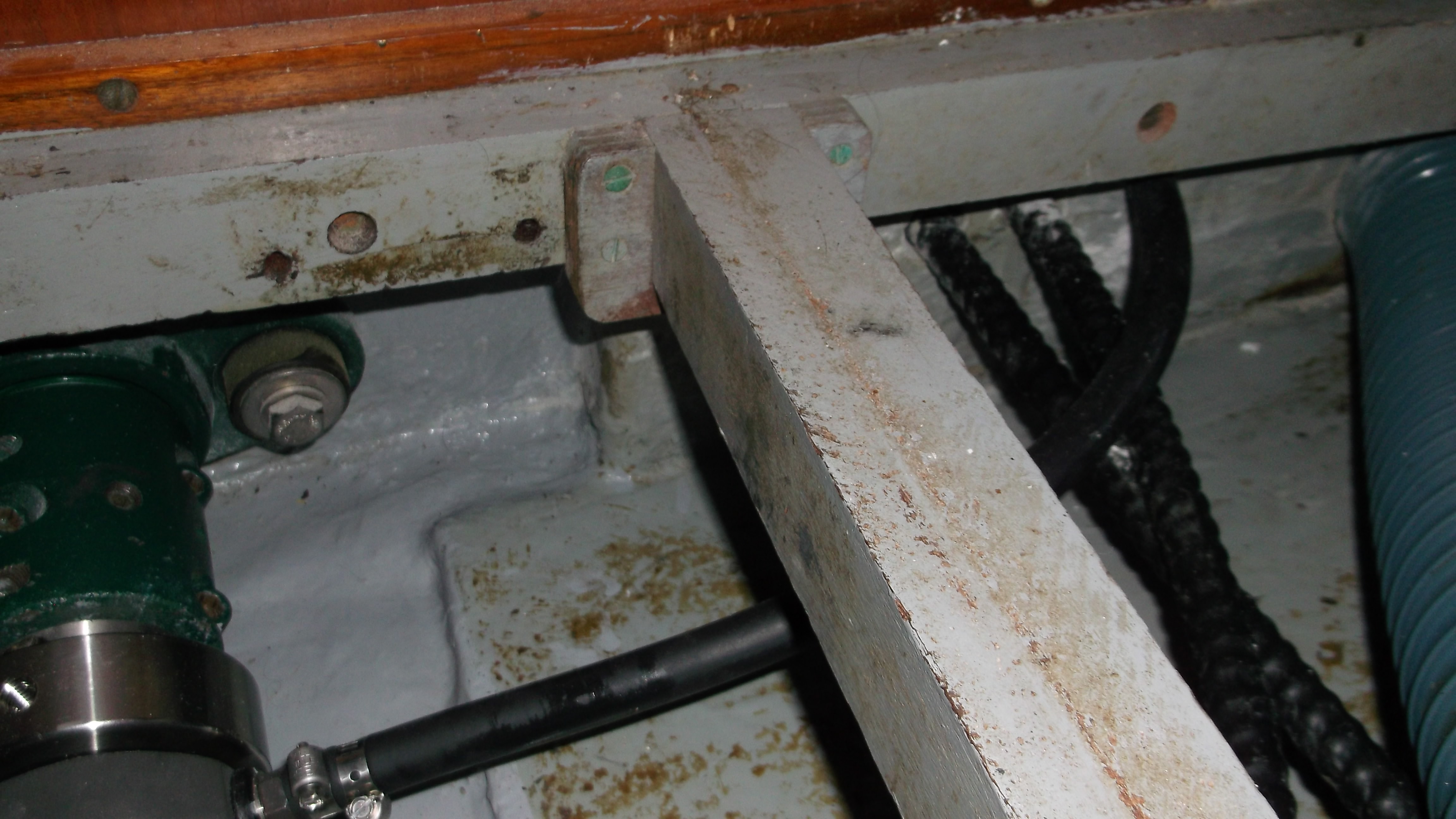
The vent hose runs over the top of the steering cables (providing support to the hose) and then through a 7/8" hole in the engine room bulkhead
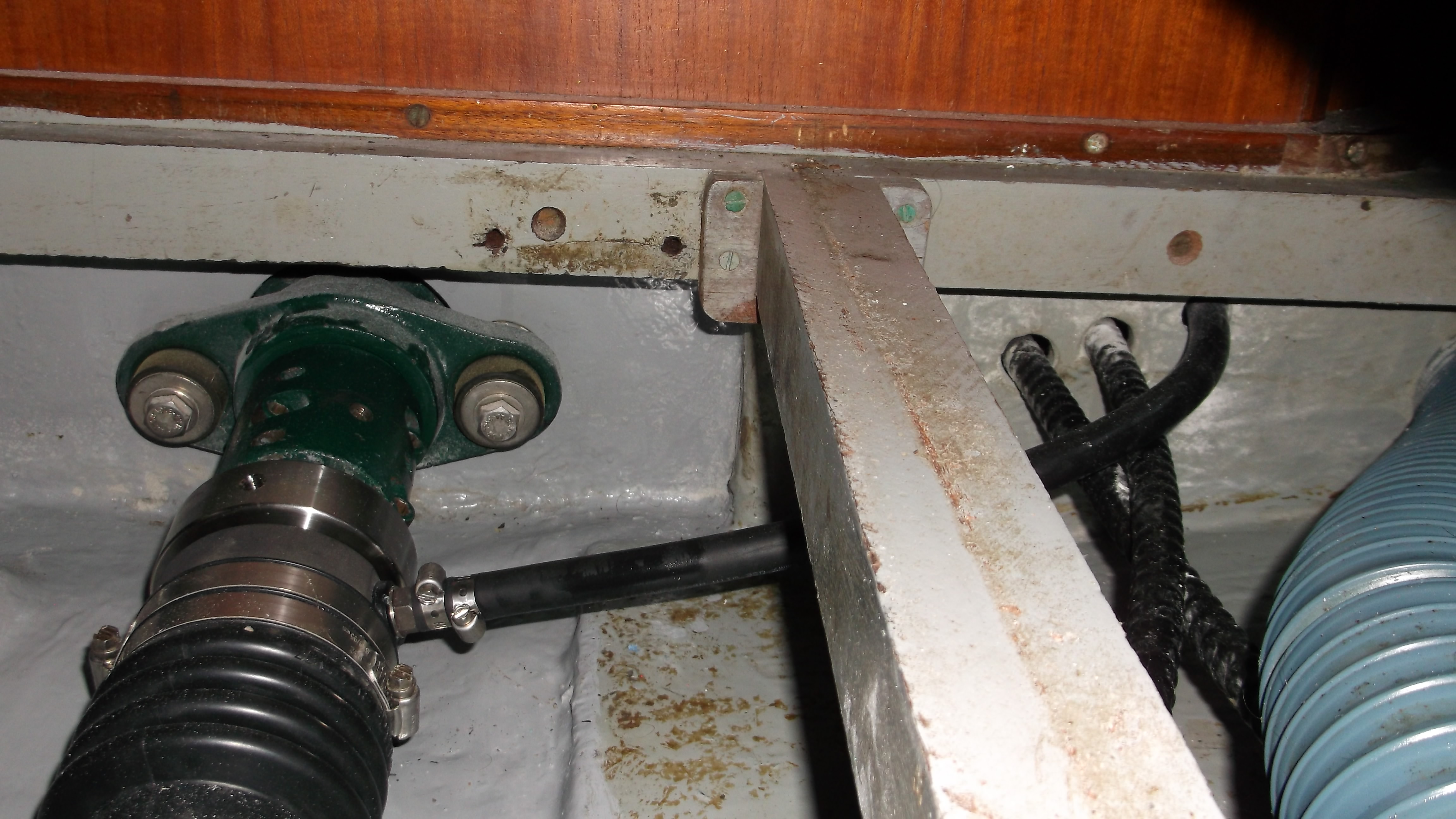
Here is a good view of the aquadrive thrust bearing assembly, the dripless stuffing box, vent tube and hole through the bulkhead with the vent line running through. The edges of the hole were carefully smoothed with sandpaper (the bulkhead is solid fiberglass at this point) to keep the hose from having any chafe as this is way below water line and a chafed hose could make for a significant leak.
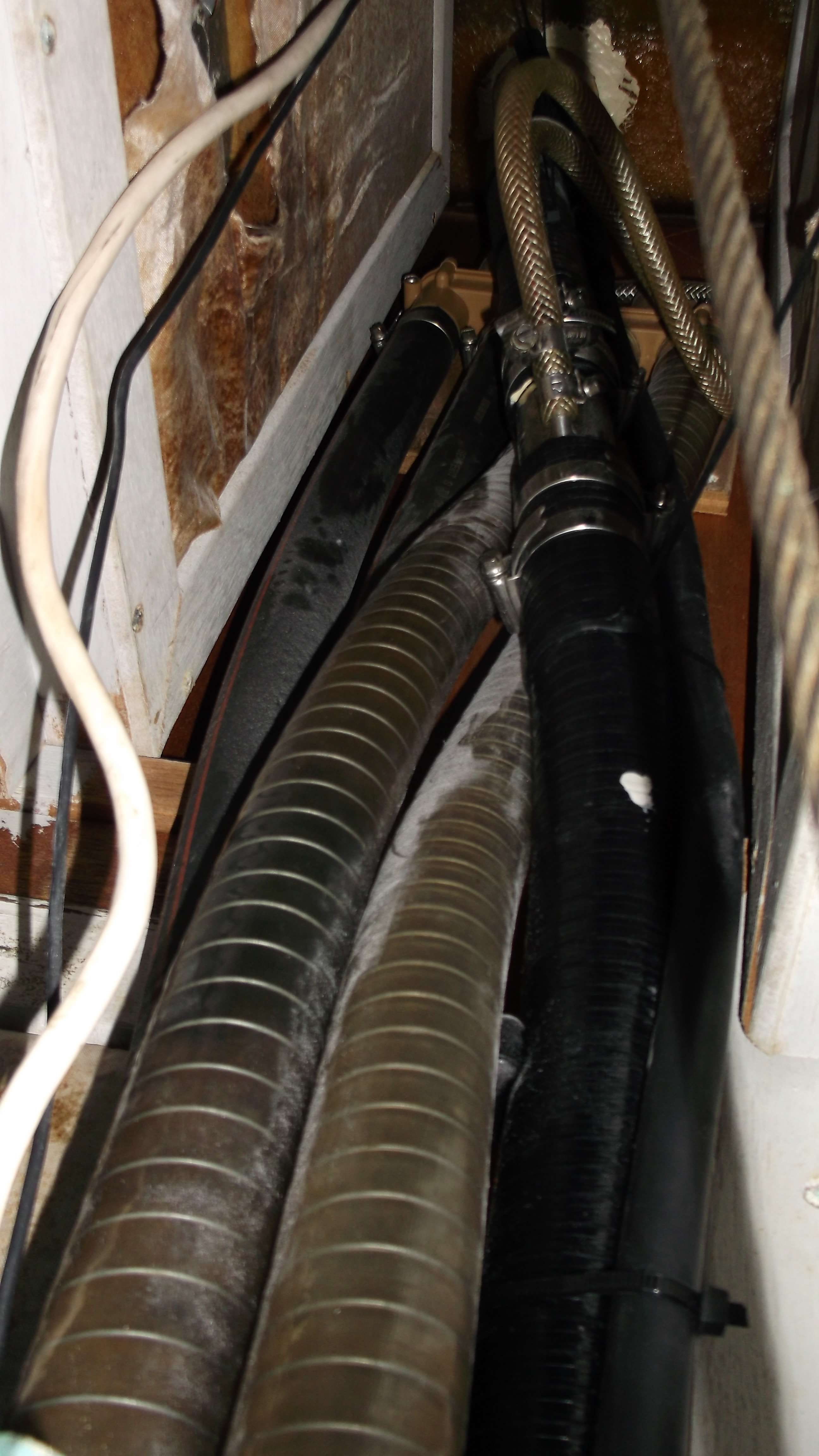
The vent line is run up to the underside of the cockpit sole. This is well above waterline. There is a real question about if it is better overall to plumb pressurized water into the stuffing box or just vent it. Both ensure that the seal remains flooded. The benefit of forced water is that the cutless bearing in the aft end of the stern tube will be flushed with the water. The downside is that there is flooding potential from the seal water backing into the raw water cooling loop. It would be installed before the vented loop into the exhaust system to avoid filling the water lift and flooding the cylinders, however, if the raw water cooling system is taken apart to replace an impeller, hose, or burn out a heat exchanger and the hose is not disconnected and capped there is some risk of flooding the boat.
The absolute need for pressure fed water starts with boats which can motor at 12 knts or more as this can create enough suction to cause the carbon seal to run dry due to the vacuum created.
In this case, I think that keeping the system simple is probably the best solution with a vent very high in the boat and not plumbed into the forced raw water cooling loop.
The first operation of the vessel did result in a ring of damp carbon dust on the bilge and the bottom of the cabin sole but this stopped within an hour of operation. I did "burp" the seal to ensure there was not any air in the seal right after launch. However, even though the vent tube is going off to the side rather than straight up it appears to be clearing the air out of the seal successfully. I would recommend burping the seal when launching but I doubt it is a significant issue in this case.
After a few hours of engine operation I decided to put a bit more compression on the bellows to tighten up the seal