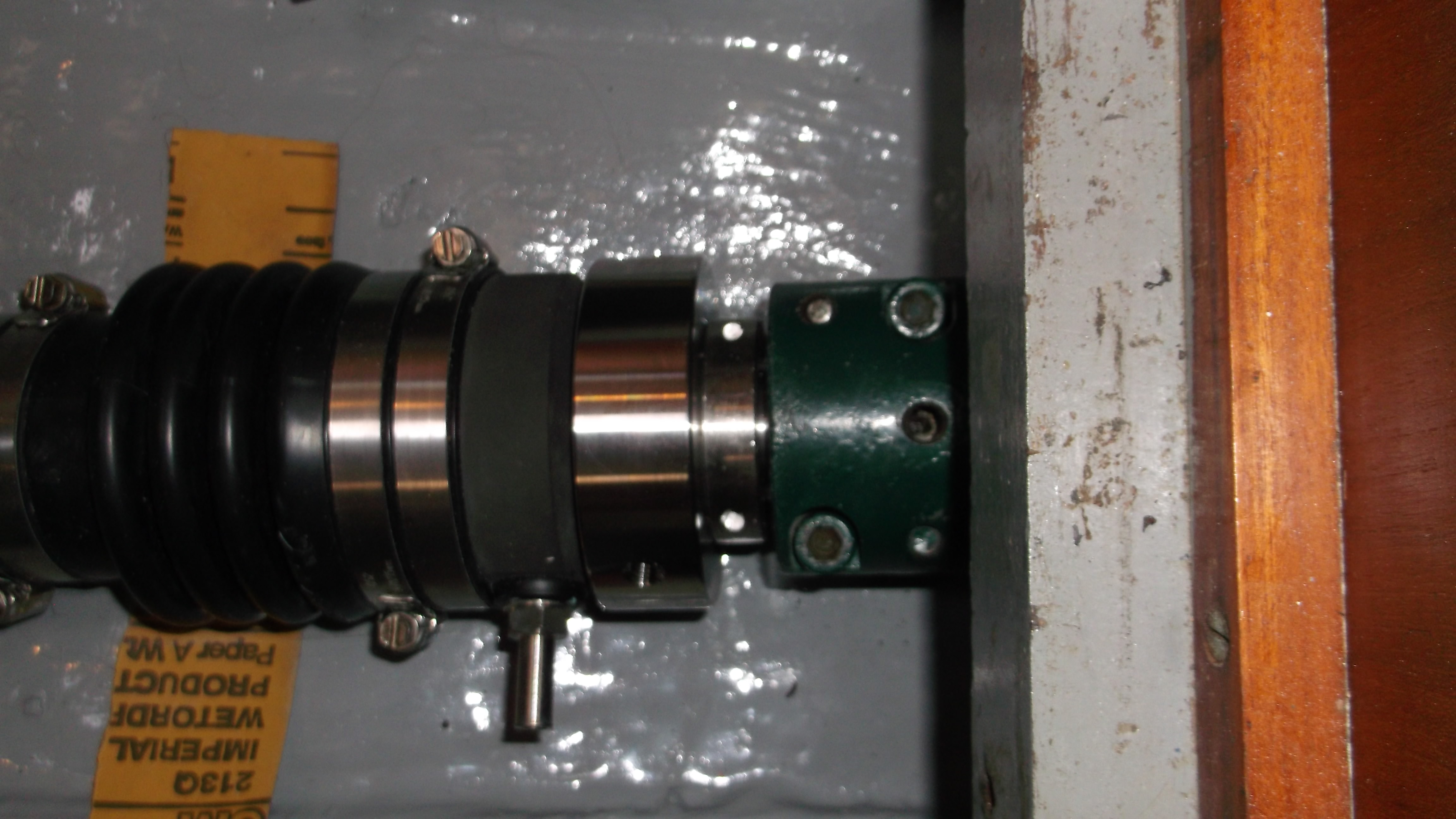
Looking down through the setscrew hole the divot for the setscrew is easily seen. I find that using a sharpie to mark the shaft lengthwise forward and aft of the setscrew divot makes it easier to keep everything aligned as it is being pushed into place. It is nearly impossible to turn the shaft on the thrust bearing clamp when it is fully installed and so keeping it aligned while being pushed home is important.
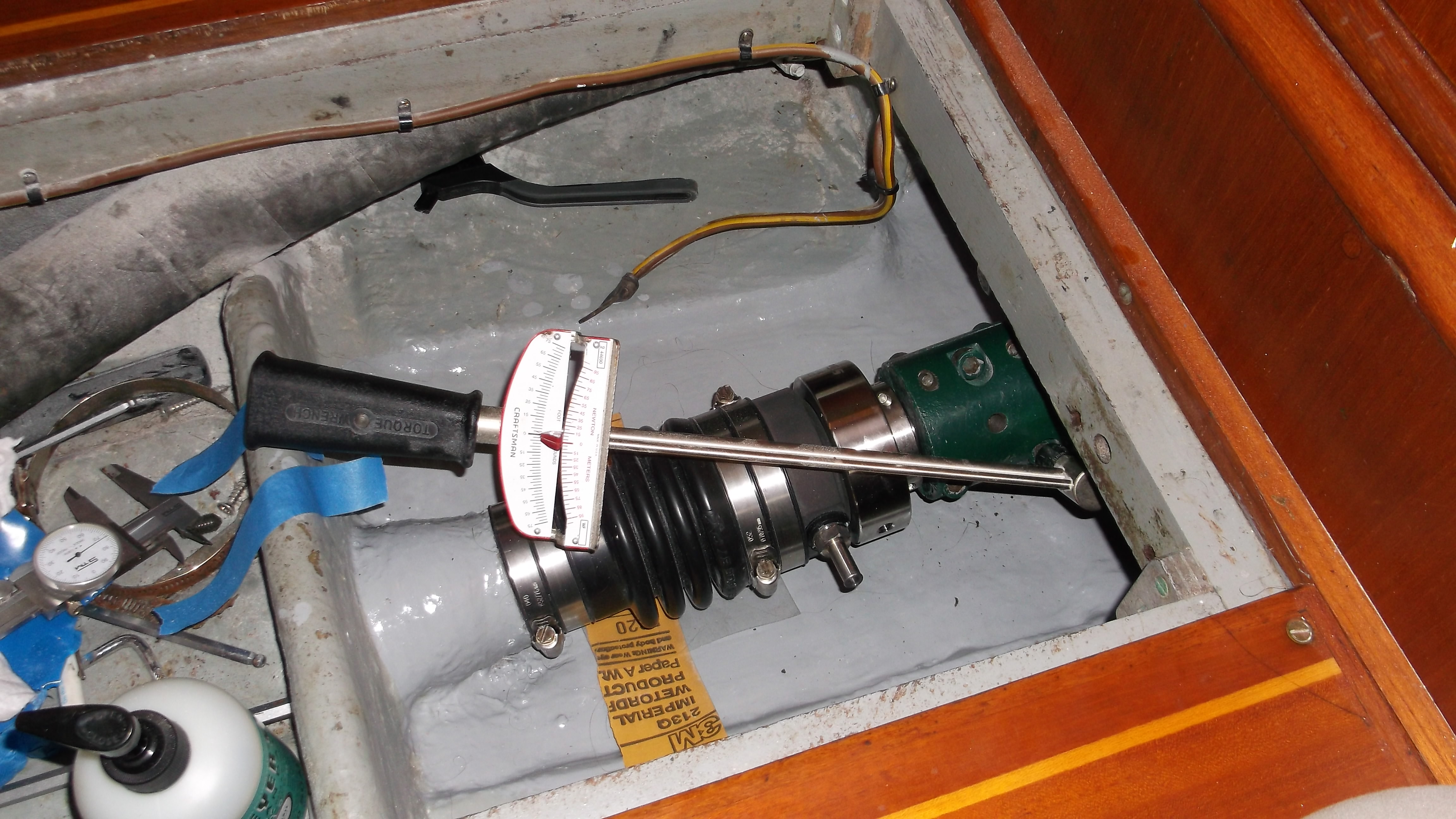
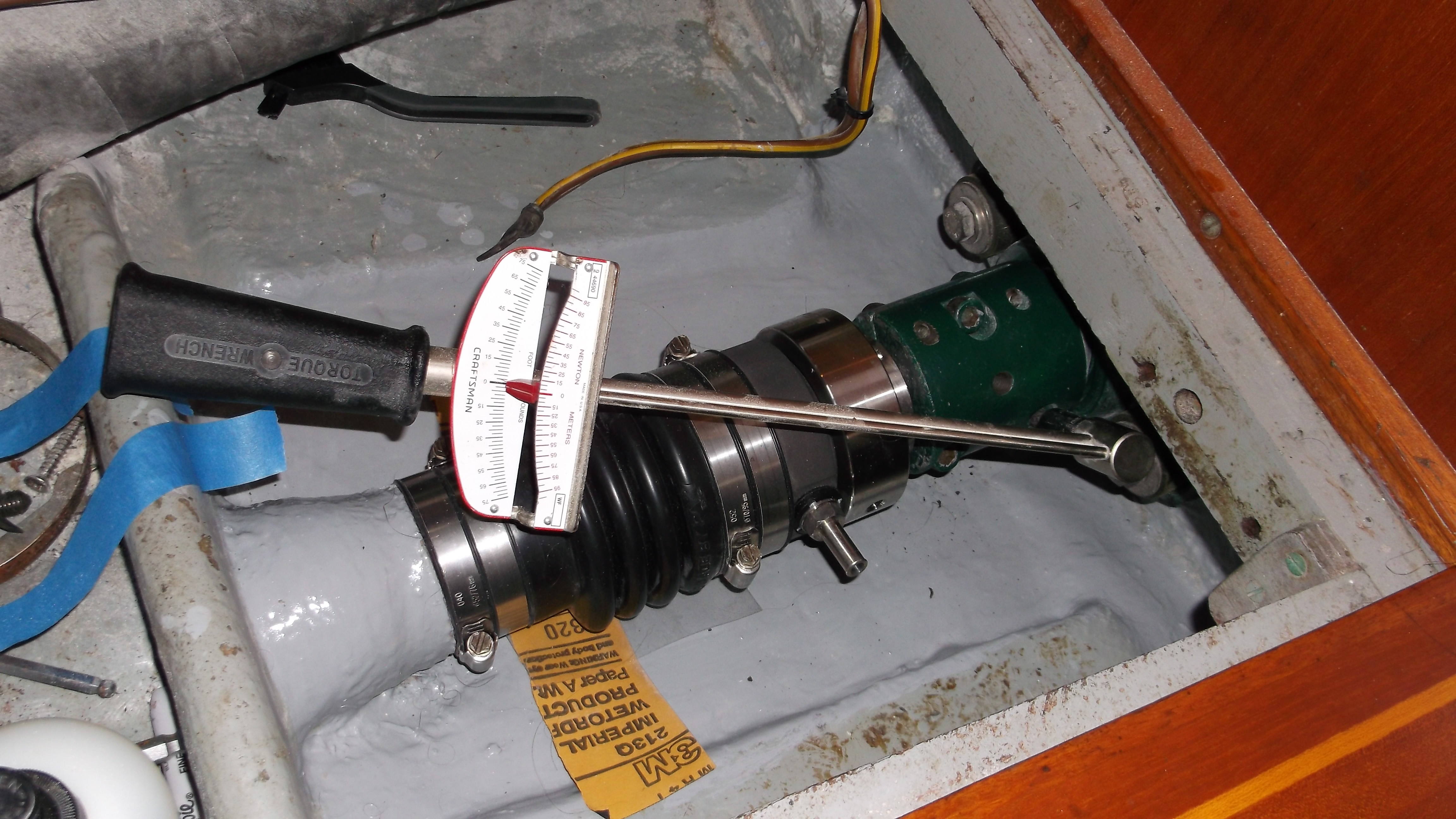
Once the divot is in the correct place the six large screws are torqued in a very specific patten and to a torque level specific to the size of the bolts. The pattern is as follows:
5 3 1
Shaft End Thrust Bearing End
6 4 2
The bolts are torqued twice, first to 25 ft-lbs of torque (this is NOT the final value). I tend to go back and recheck the torque of each bolt after everything is at this level although it is most likely overkill.
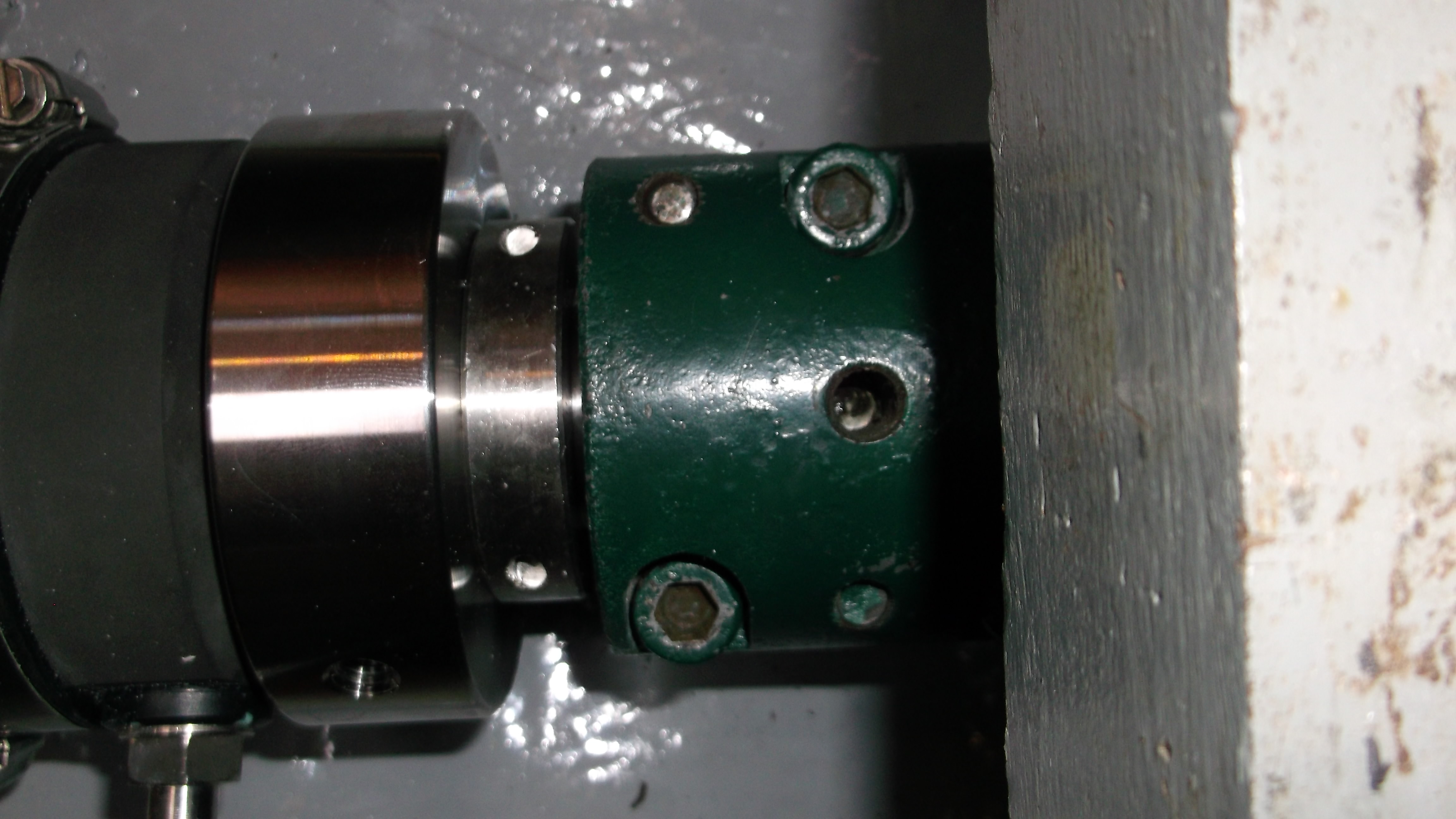
Then it is important to re-verify that the divots of the shaft are in the correct positions, here is one side.
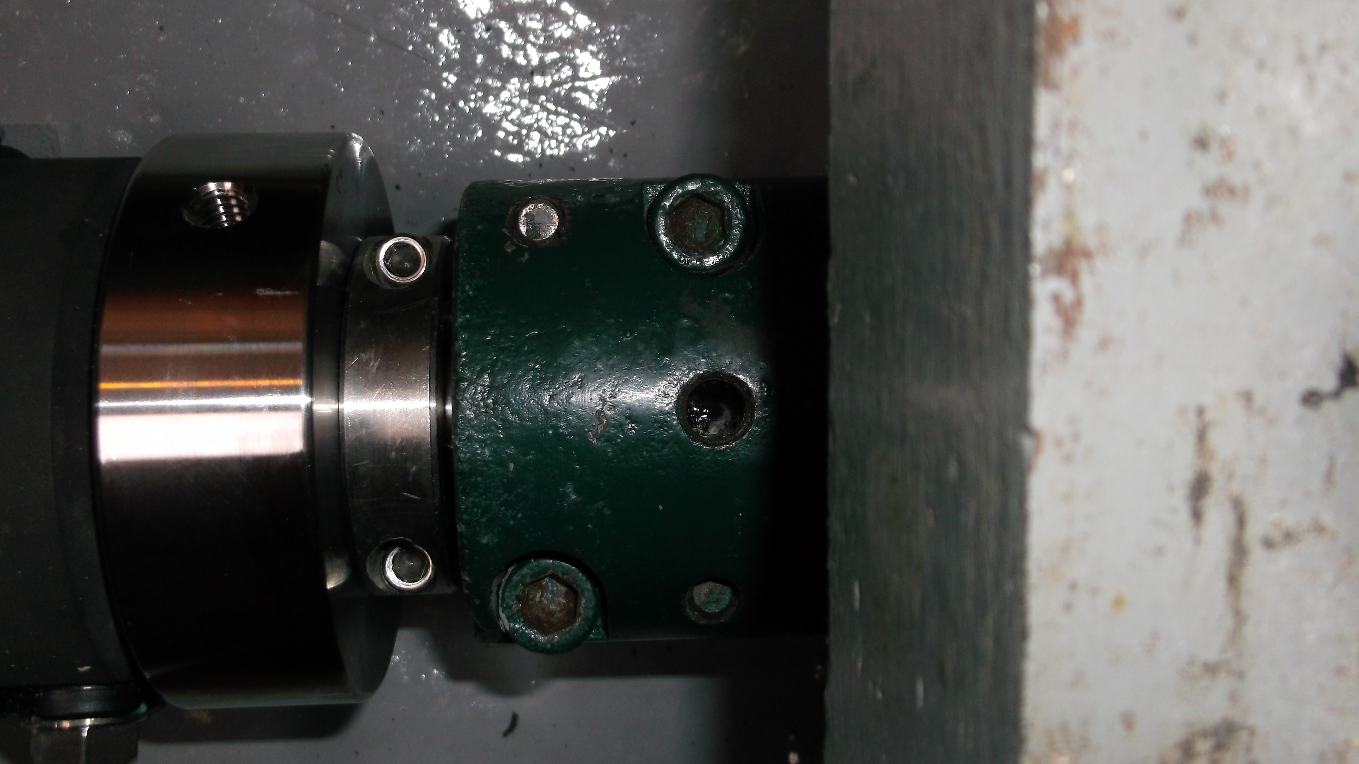
Then I turn the shaft over and verify the other side.
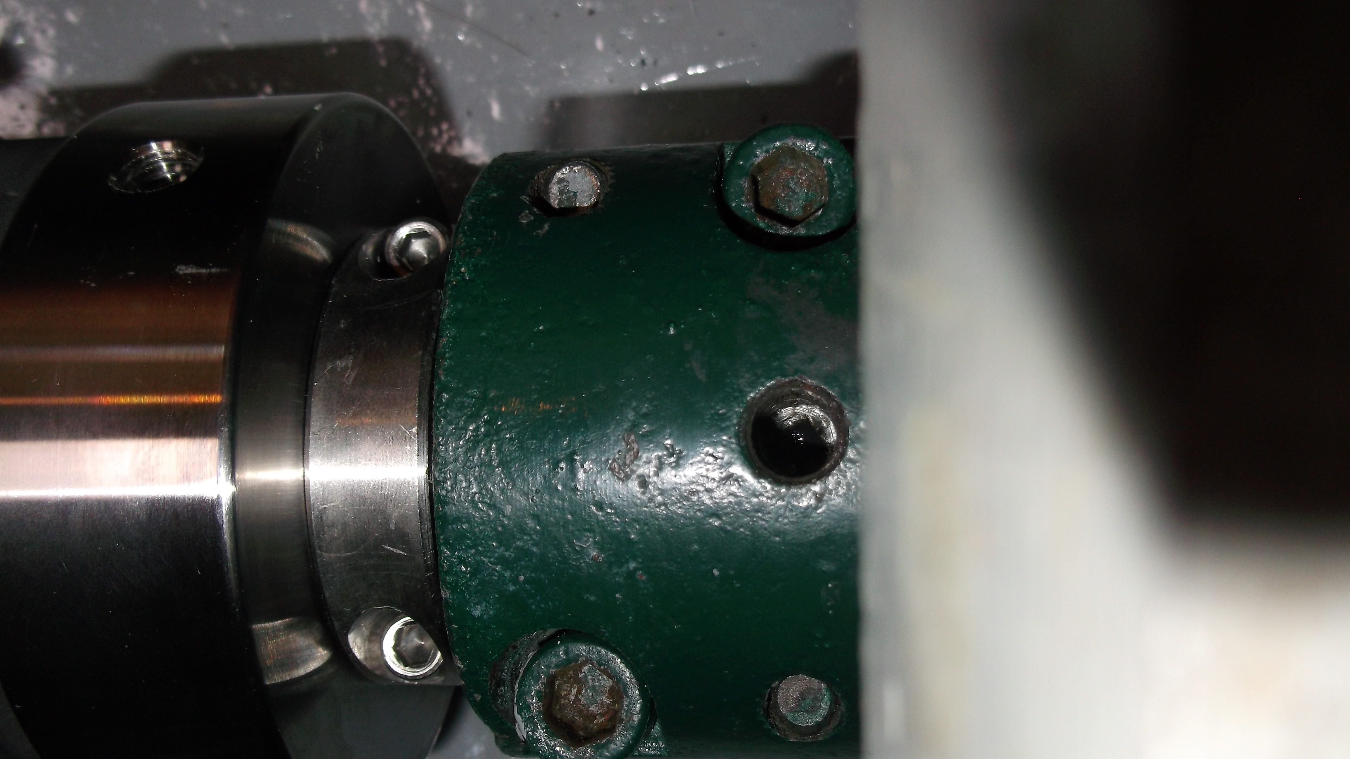
It is very important to look closely and verify that the divot is carefully centered in the hole for the setscrew.
Once the divots are verified to be in the correct orientation, the six large screws are torqued in the same specific patten and to a final torque level specific to the size of the bolts. The pattern is the same as above:
5 3 1
Shaft End Thrust Bearing End
6 4 2
The bolts are torqued to the final value of 49 ft-lbs (i.e. 50 ft-lbs, the manual is a conversion from metric). I tend to go back and recheck the torque of each bolt after everything is at this level although it is most likely overkill.
Finally the setscrews are installed in both holes snuggly to ensure the shaft does not try to rotate int he flange.
I will plan to come back with external locking material which cracks if the large cap-screws move to verify that the cap-screws have not moved as this is potentially a high vibration environment. If the flange were to become loose the shaft could be pulled out of the back of the boat in reverse. The extra clamp on the shaft is an added level of safety to ensure that does not happen.