October 8, 2011
The original gate valves were connected to a "custom" piece of copper piping which formed a 'T' for connection to the fresh water pump. The threads on all of the components were BTT (i.e. British Tapered Thread) connected to the tanks with pieces of 1 1/4" flexible hose. The gate mechanisms for both valves did not work consistently and would not close completely so there was always an amount of water moving between the two tanks. Not enough to cause significant issues just enough to know that water was slowly moving.
The original fresh water manifold as it was installed
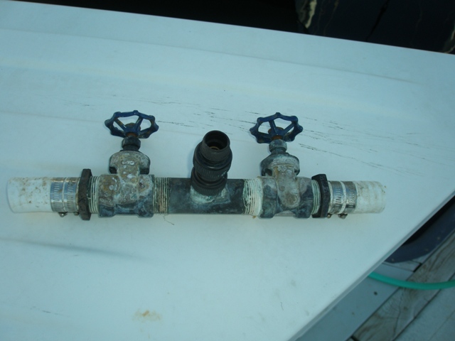
This is the original freshwater manifold. There is significant corrosion as this is above the bilge which occasionally has salt water in it. The threads are British Tapered Threads and were frozen sufficiently badly to make replacement difficult. Thus it was time to make a new piece instead of rebuilding the existing part.
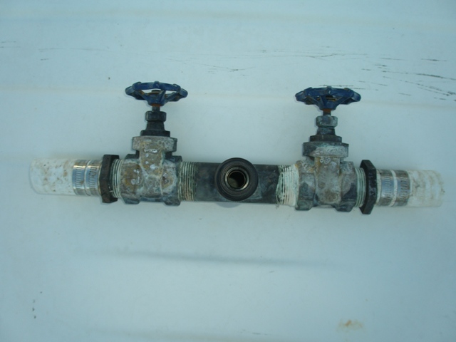
Here we can see that the connection to the water system was accomplished by brazing a piece of pipe to another piece of pipe to make a relatively close T. These parts being pretty close together makes building this hardware up out of pieces a bit challenging but not impossible. Also, the inside of this piece of hardware was not easy to get completely clean and had some level of biological growth / surface contamination which was contributing to the taste of the water tanks not being as good as it could be.
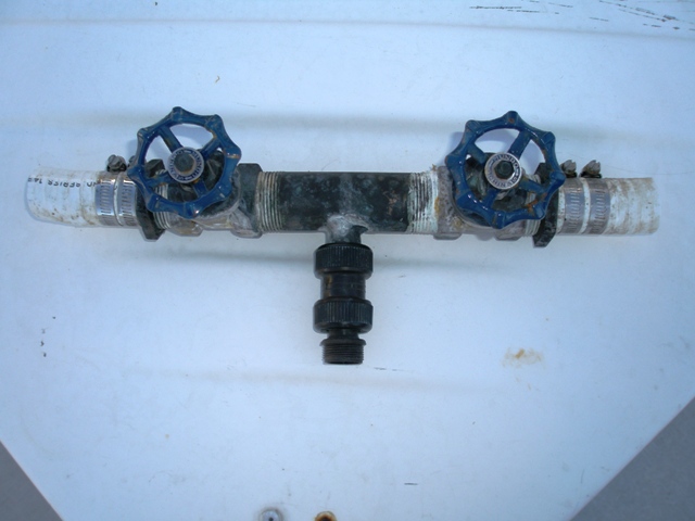
The way that this manifold ends up being situated the outlet of the manifold is definitely the lowest point in the fresh water system meaning that all of the water in the tanks is accessable.
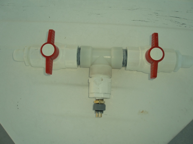
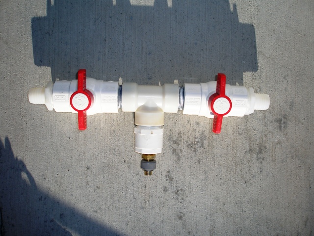
Here I have managed to build up the same manifold using 1 1/2" PVC ball valves. The short nipples are of sechedule 80 (thick wall) pipe and the T is a nylon part from West Marine. Fitted into the bottom of the T is a 1 1/2 inch thread to slip pipe and then a slip pipe to 1/2" thread. The slip pipe to thread has a very nice 45 degree slope inside which results in no place for contamination to build up. The nylon hose barbs are 1 1/2" thread to 1 1/4 inch pipe. Finally the connection from thread to 15mm whale piping system completes the assembly. The entire piece is a bit wider than the original piece and thus getting the hose into place is a bit tricky but in the end it all came together very nicely.
If I had to do it again I might have been tempted to build up the entire assembly out of PVC slip fitting parts which would have the potential to have two connections out of the bottom and a second valve between the two sides. This extra complication would allow for two completely independent freshwater systems, one for showers, toilets, sinks, etc. The other for drinking water and the drinking water tank would be the one which the watermaker would feed into.
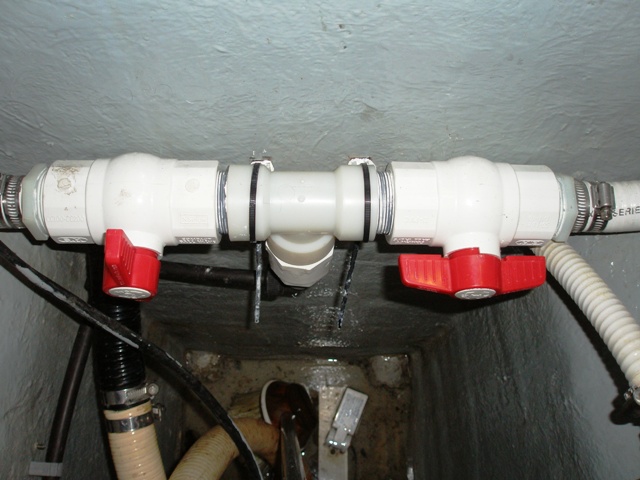
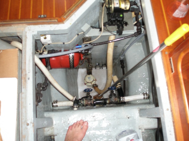
Here is the new freshwater tank installed between the two water tanks. I had intended to use the better quality hose clamps which do not have cuts in the hose clamps. However, 1 1/4 inch hose is just between two sizes and resulted in a very long "tang" on the hose clamp sticking out which could catch on someone working in the bilge so I opted for the other style in this case. All connections are double hose clamped and all of the threaded connections were covered with pipe thread paste to ensure they would not leak.
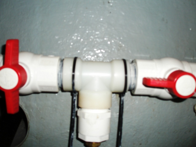
Here is a closeup of the installed fresh water manifold. Just under the manifold to the left is the hole through the stringer for the bilge pump lines. Above and to the right is the hole for the holding tank vent. Two cable tie holders screwed into the stringer (with polysulfide sealant on the threads) hold the assembly in the desired location, however, if the hose clamps were to break the assembly would not move significantly.